Swing
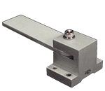
A circular motion of functional parts attached on / suspended from the board


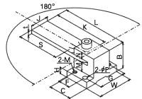
1. Inplane and circular movement against face
2. Scale with every 10°
3. Amplitude 180°
2. Scale with every 10°
3. Amplitude 180°
| Part No. | J | S (valid) |
K | t | M | N | B | C | H | W | L | F | G | 2-φP | 2-M | Cap screw |
movable load N |
|---|---|---|---|---|---|---|---|---|---|---|---|---|---|---|---|---|---|
| MBX10-50 | 10 | 42 | 50 | 3 | 5 | 4 | 16.5 | 16 | 4.5 | 24 | 61 | 8 | 18 | φ3.5 | M3 | M4 | 13 |
| MBX10-75 | 67 | 75 | 86 | 11 | |||||||||||||
| MBX20-60 | 20 | 47 | 60 | 4 | 9.5 | 7.5 | 28.5 | 25 | 7.5 | 38 | 79 | 13 | 30 | φ4.5 | M4 | M5 | 18 |
| MBX20-90 | 77 | 90 | 109 | 15 | |||||||||||||
| MBX30-70 | 30 | 51 | 70 | 5 | 15 | 10 | 40.5 | 36 | 10.5 | 52 | 96 | 20 | 42 | φ5.5 | M5 | M6 | 19 |
| MBX30-100 | 81 | 100 | 126 | 18 |


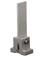
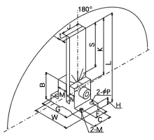
1. Vertical and circular movement against face
2. Scale with every 10°
3. Amplitude 180°
2. Scale with every 10°
3. Amplitude 180°
* withholding load = edge position
| Part No. | J | S (valid) |
K | t | M | N | B | C | H | W | L | F | G | 2-φP | 2-M | Cap screw |
movable load N |
|---|---|---|---|---|---|---|---|---|---|---|---|---|---|---|---|---|---|
| MBY10-50 | 10 | 37 | 50 | 3 | 8 | 5 | 22.5 | 20 | 6.5 | 32 | 66.5 | 13 | 25 | φ3.5 | M3 | M4 | 49 |
| MBY10-75 | 62 | 75 | 91.5 | 26 | |||||||||||||
| MBY20-60 | 20 | 46 | 60 | 4 | 10 | 6 | 28.5 | 7.5 | 38 | 80.5 | 30 | M5 | 109 | ||||
| MBY20-90 | 76 | 90 | 110.5 | 71 | |||||||||||||
| MBY30-70 | 30 | 51 | 70 | 5 | 15 | 10 | 40.5 | 30 | 10.5 | 52 | 100.5 | 16 | 42 | φ5.5 | M5 | M6 | 192 |
| MBY30-100 | 81 | 100 | 130.5 | 177 |
※You may download 3D CAD drawings by clicking on the part number of interest.


