


Complying with JIS & Original Type
The standard joint which is used in industrial equipment.


![]()
![]()

※Please choose new JIS key, the old JIS key
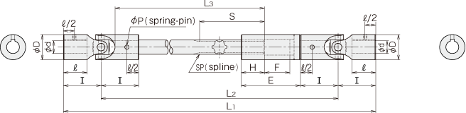
■Type B-P Dimension Table
standard part's attachment : spring-pin 4 pieces
| φdH7 | φD | Ⅰ | ℓ | E | H | F Slide distance |
φA | S | SP | Dimension of spring-pin for fixing |
New JIS key | Old JIS key | TAP M |
MAX | MIN | |||||
|---|---|---|---|---|---|---|---|---|---|---|---|---|---|---|---|---|---|---|---|---|
| aJS9 | b | aJS9 | b | L1 0 -F |
L2 | L3 | L1 0 -F |
|||||||||||||
| B-6P | 6 | 12 | 25 | 18 | 43.5 | 8.5 | 25 | 6 | 60 | Large diameter6 m=0.5 z=10 |
2×12 | 2 | 1.0 | 2 | 1.0 | M3 | 266.5 | 216.5 | 150 | 168.5 |
| B-8P | 8 | 16 | 28 | 19 | 50.5 | 10.5 | 25 | 8 | 70 | Large diameter8 m=0.5 z=14 |
2.5×16 | 3 | 1.4 | 3 | 1.5 | M3 | 433 | 377 | 300 | 187.5 |
| B-10P | 10 | 20 | 34 | 23 | 65 | 20 | 30 | 10 | 80 | Large diameter10 m=0.5 z=18 |
3×20 | 3 | 1.4 | 4 | 1.5 | M4 | 458 | 390 | 300 | 231 |
| B-12P | 12 | 24 | 42 | 29 | 85 | 25 | 35 | 12 | 80 | Large diameter12 m=0.75 z=14 |
4×25 | 4 | 1.8 | 4 | 1.5 | M4 | 599 | 515 | 400 | 288 |
| B-14P | 14 | 28 | 47 | 31.5 | 90 | 25 | 40 | 14 | 65 | 11×14×3×6 | 5×28 | 5 | 2.3 | 5 | 2.0 | M5 | 621.5 | 527.5 | 400 | 318 |
| B-16P | 16 | 32 | 52 | 34.5 | 95 | 30 | 40 | 16 | 75 | 13×16×3.5×6 | 5×32 | 5 | 2.3 | 5 | 2.0 | M5 | 638.5 | 534.5 | 400 | 343 |
| B-18P | 18 | 36 | 60 | 40 | 105 | 35 | 45 | 20 | 85 | 16×20×4×6 | 6×35 | 6 | 2.8 | 5 | 2.0 | M6 | 870 | 750 | 600 | 390 |
| B-20P | 20 | 40 | 62 | 40 | 110 | 40 | 45 | 22 | 90 | 18×22×5×6 | 6×40 | 6 | 2.8 | 5 | 2.0 | M6 | 878 | 754 | 600 | 403 |
| B-22P | 22 | 44 | 65 | 41 | 115 | 40 | 50 | 25 | 95 | 21×25×5×6 | 6×45 | 6 | 2.8 | 7 | 3.0 | M8 | 1094 | 964 | 800 | 425 |
| B-25P | 25 | 50 | 70 | 43 | 125 | 40 | 60 | 30 | 100 | 23×28×6×6 | 8×50 | 8 | 3.3 | 7 | 3.0 | M8 | 1122 | 982 | 800 | 465 |
| B-30P | 30 | 60 | 89 | 56 | 140 | 55 | 60 | 35 | 115 | 28×34×7×6 | 10×60 | 8 | 3.3 | 7 | 3.0 | M8 | 1185 | 1007 | 800 | 556 |
・MAX L1 = Maximumlengthin which the sliding stroke F of standard part is kept.
・MIN L1=Minimum length in which a shaft and a sleeve are cut and the engaged distance H and sliding stroke F are kept.
※You may download 3D CAD drawings by clicking on the part number of interest.