


Complying with JIS & Original Type
The standard joint which is used in industrial equipment.


![]()
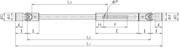
■Type M-L Dimension Table
| φdH7 | φD | Ⅰ | ℓ | E | H | F Slide distance |
φP | MAX | MIN | |||
|---|---|---|---|---|---|---|---|---|---|---|---|---|
| L1 0 -F |
L2 | L3 | L1 0 -F |
|||||||||
| M-2.0L | 2.0 | 6 | 7.5 | 4 | 35 | 5.75 | 18 | 1.5 | 95 | 80 | 42.3 | 83 |
| M-2.5L | 2.5 | |||||||||||
| M-3.0L | 3.0 | 6 | 9 | 5.5 | 35 | 5.75 | 18 | 1.5 | 100 | 82 | 43 | 89 |
| M-3.5L | 3.5 | |||||||||||
| M-4.0L | 4.0 | 8 | 12 | 7.2 | 44 | 8 | 24 | 2.0 | 150 | 126 | 77.2 | 116 |
| M-4.5L | 4.5 | |||||||||||
■Spline dimension (large diameter 5 m=0.5 z=8) Refer to join slide SPS series in page 20 |
||||||||||||
| M-5.0L | 5.0 | 10 | 15 | 9 | 42.5 | 7.5 | 25 | - | 200 | 170 | 114 | 127.5 |
| M-5.5L | 5.5 | |||||||||||
・MAX L1 = Maximumlengthin which the sliding stroke F of standard part is kept.
・MIN L1=Minimum length in which a shaft and a sleeve are cut and the engaged distance H and sliding stroke F are kept.
※You may download 3D CAD drawings by clicking on the part number of interest.